|
|
|
|
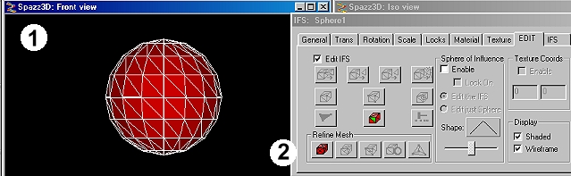
Index Face Set Editor & the Sphere of InfluenceO.K. , I still recall the whole unease of using the IFS editor when I first got started. Mr P's tutorial is of course absolutely correct when it states that this is a very powerful tool in your VRML arsenal (paraphrased). The following tutorial is something I've put together as an illustrated step by step approach to exploring a couple of very dynamic features of the IFS editor. I have no intention of trying to sum up every single function, Like Mr P, I still discover new tricks using Flux Studio even now. Hopefully for those who are still a bit raw with IFS manipulation, the following will be a useful pointer. OK ramblers, let's get rambling. Fire up Flux Studio and drop a sphere primitive in your top viewport. The scale isn't important here. Make sure you have a decent view of it. Now go to "Edit " in the top menu bar, scroll down (Make sure your sphere is selected) now choose the option " convert to IFS". After completing this you should have "IFS Sphere1" as your new on screen node and see something pretty much like step one...
The act of converting to an IFS will open up the dialogue box as above on the right, click the edit tab and note the button next to (2) in the diagram, refine mesh.
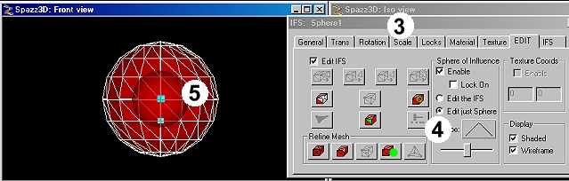
Select front view for your IFS sphere as shown and click your mouse over the centre vertex of the IFS Sphere, tick the box that says "Enable" in the sphere of influence option. The Sphere of influence (Lets call it SOI) is the same size as your IFS Sphere so click "Edit just sphere" (4) then open "Scale" tab (3) and enter 0.5. Click that central vertex again and you should see something exactly like (5).
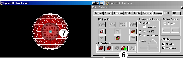
If you used the SOI right now and pulled the ball away from the IFS sphere you'd get a really rough looking extrusion, we don't want that, so press the button (6) with the little green ball on it a couple of times. This has refined all edges inside the scaled SOI so you should see an inner lattice as shown in (7). So far all of this has affected the SOI and made very little difference to the IFS model.
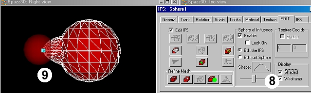
So what we will do now is switch the view so we have a side profile of the IFS, choose to view "Right view" You should see the IFS sphere, its SOI and the handle of the central vertex we selected . In the IFS editor switch to "Edit the IFS" then move the "Shape slider " to show a curve like the one next to (8). Now pull the SOI ball by the little vertex handle gently to the left. The result should look something like (9). Note how the bulging surface matches accurately the curve shown in the "Shape" box. Its worth pressing the undo button the doing this step all over again this time moving the shape slider to create a different shape. Hopefully each time you do this, You'll see the exact relationship between the shape shown in the "Shape".
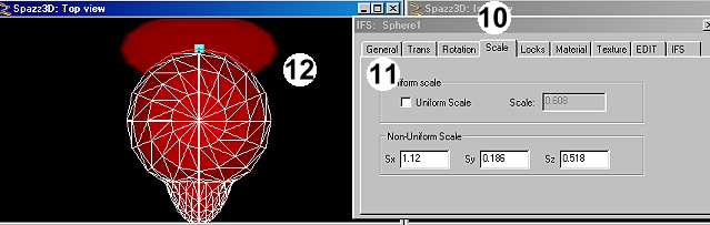
In the next step we need to back pedal and do the same thing as we did in Step 2 except this time well select the central vertex on the back of the IFS sphere. We won't need to scale the SOI down again because Its already at 0.5. What we will do is choose the scale tab (10) untick "Uniform scale" (11) the either enter the following values Sx 1.12 Sy 0.186 Sz 0.518. Alternatively, moving the mouse over your active viewport will show that the pointer has the "Scaling" arrows (Did you remember to tick "Edit Sphere of influence only" ?) You can pull the arrows over the sphere and watch it become another shape. In your viewports you'll see that you now have an oval, flat shape instead of an SOI (12), you've flattened it. Repeat the same steps as above, refine faces within the sphere of influence a couple of times.
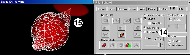
This time I moved the shape slider (14) to make a point of sorts then selected "Edit the IFS" and pulled my flattened SOI in the other direction. In illustration 15 the relationship between the SOI Shape slider and how it affects the node are very clearly expressed. The techniques above can apply to any shape that you convert into an IFS, it certainly allows you to begin to see the potential of this great modeling tool. Here is another nifty little trick...
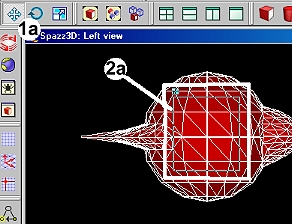
Make sure the select icon is selected (1a), switch to left view and click in the blackness surrounding your IFS shape so that nothing is selected. Look at the white box I've drawn in (2a). In the top left corner, still in "Select mode", I clicked and dragged from the centre of a triangle face down to the bottom right. You should see from the illustration that there is a thin lined square in box (2a) let go of the mouse and ...
the vertices in my selection have now been selected in a square formation. The little white handles show that 9 vertices have been chosen .
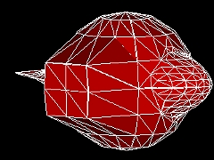
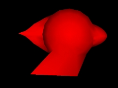
So with those vertices selected I pulled them away from the IFS (In this example I also hit the button "Move all selected vertices into a common plane"), this has given me a flat edged shape extending from the IFS ball. As those vertices were still selected after I'd pulled them away from the IFS, what I then did was clicked the scale tab, selected non- uniform scale and dragged my mouse over the selected face. This in turn allowed me to turn the selected square of vertices into a selected rectangle of vertices.
What an odd shape! Its certainly not the IFS sphere we had a few moments ago. Hopefully this demonstrates with ease how you could begin complex modeling. Another very useful feature in the IFS editor is "Crease angle" by default it is always set at 30, with my shape I maxed it up to 60 to create a smoother look. You could of course go to an opposite extreme and choose 0.1 to get a really angular anti-smooth effect. I'd recommend that you try to aim for low polygons when modeling, try to abstain from refining the mesh more than you have to. Remember, when you add more triangles to a shape, you are bumping up the file size and processing resources which can work well, but can also be responsible for cumbersome work on other people's machines. Hope this has helped a little in your understanding of the SOI and IFS editor. |
|
|